After a brief phone call with Ed G, I got enough energy to dig back into the scrambler project. That, and the Norton project has come to a short holding pattern. the last few things to get into on the scrambler are the broken screws on the oil pump, check the main bearings condition and open the gear box for inspection. with all of theses the engine needed to be pulled. I needed to gather thoughts as far as approaching the oil lines which snake around and behind the frame. As simple as two oil lines and a vent tube are; they were well convoluted.


Once the oil lines were well documented, I could get onto removing the primary drive case and clutch unit.


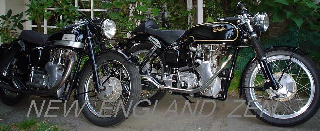
Here is a detail of the output/input of the transmission including the 'frying pan' throw out minus the bearing that rides within the gate. I rather like the design, its very simple and works well when all the bits are in good nick.


When adjusting up a Velo clutch, disconnect the cable and thread the ring at the clutch in until you feel a slight slip on compression while operation of the starter lever and only just slip. At that point you can re connect the clutch cable; there should be an adjuster inline of the cable housing, wind this adjuster to make sure you have extra slack to start the whole adjustment of the cable housing before connecting the cable
Connect the cable to the hand lever, then using the inline adjuster, remove any extra slack in the cable housing. The more time spent feeling the proper adjustment of no free play without over doing it,the better. Make sure to move the cable about and double check that you've remove any slackness that was added while the cable was disconnected. Do not wind the adjuster so tight that you need wrenches.
Now the final adjustment is carried out at the clutch; the threaded ring is wound out and as this is done you should feel free play coming back to the hand lever (with light pressure) remember the three pins, as the ring is wound out they now gain room to move. The adjustment is complete when there is about 1/8 inch gap of free play at the lever. The whole reason for this 'process' is that Veloce had gone to great lenghts toward making such a thin clutch operate in such a small space; the adjustment is right on the edge of motion for a slipping action. It is a refined engineered device with almost pinpoint accuracy.


